Mai 2020
Holing out after Crossing Sydney Harbour
Sydney Metro is the biggest public transport project in Australia, and it is currently being extended to cover the City and Southwest districts of Sydney.
Click here to jump to the testimonial statement.
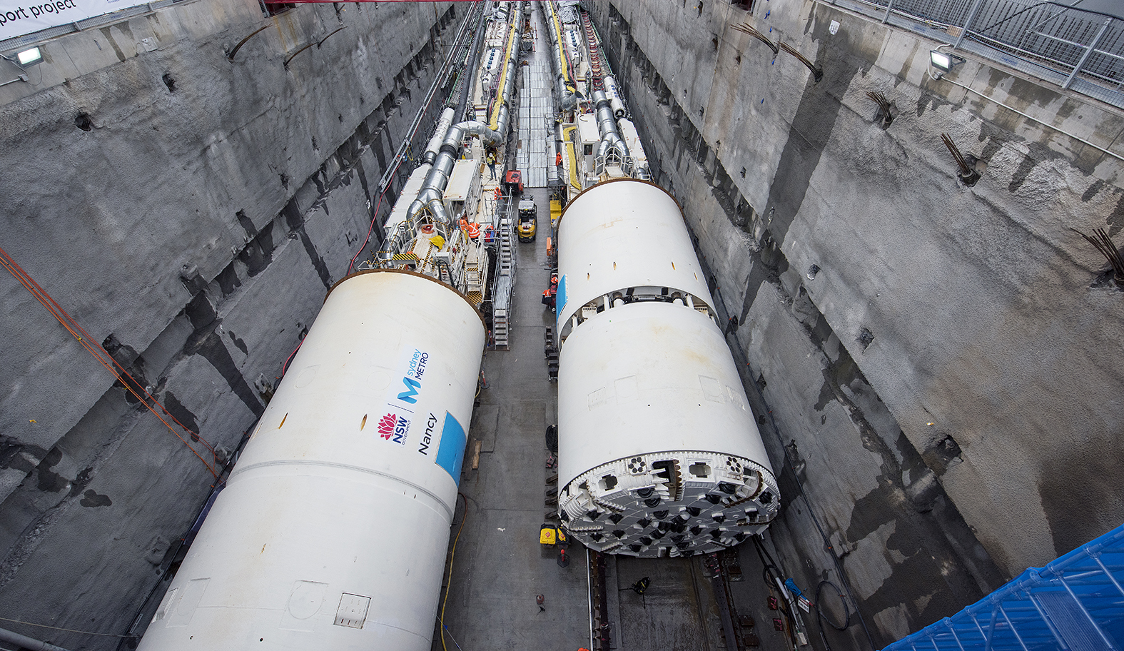
The current work program involves the construction of 15.5 km twin tunnel using five (5) Tunnel Boring Machines (TBMs) working concurrently across the tunnel route. Four TBMs are Herrenknecht double shield machines and one single shield machine. Other sections of the tunnelling works, mainly for the station cavern construction, involve the use of 13 roadheader machines along with seven (7) rockbolter rigs. The tunnelling works are being carried out by the joint venture tunnelling contractor John Holland CPB Ghella Joint Venture.
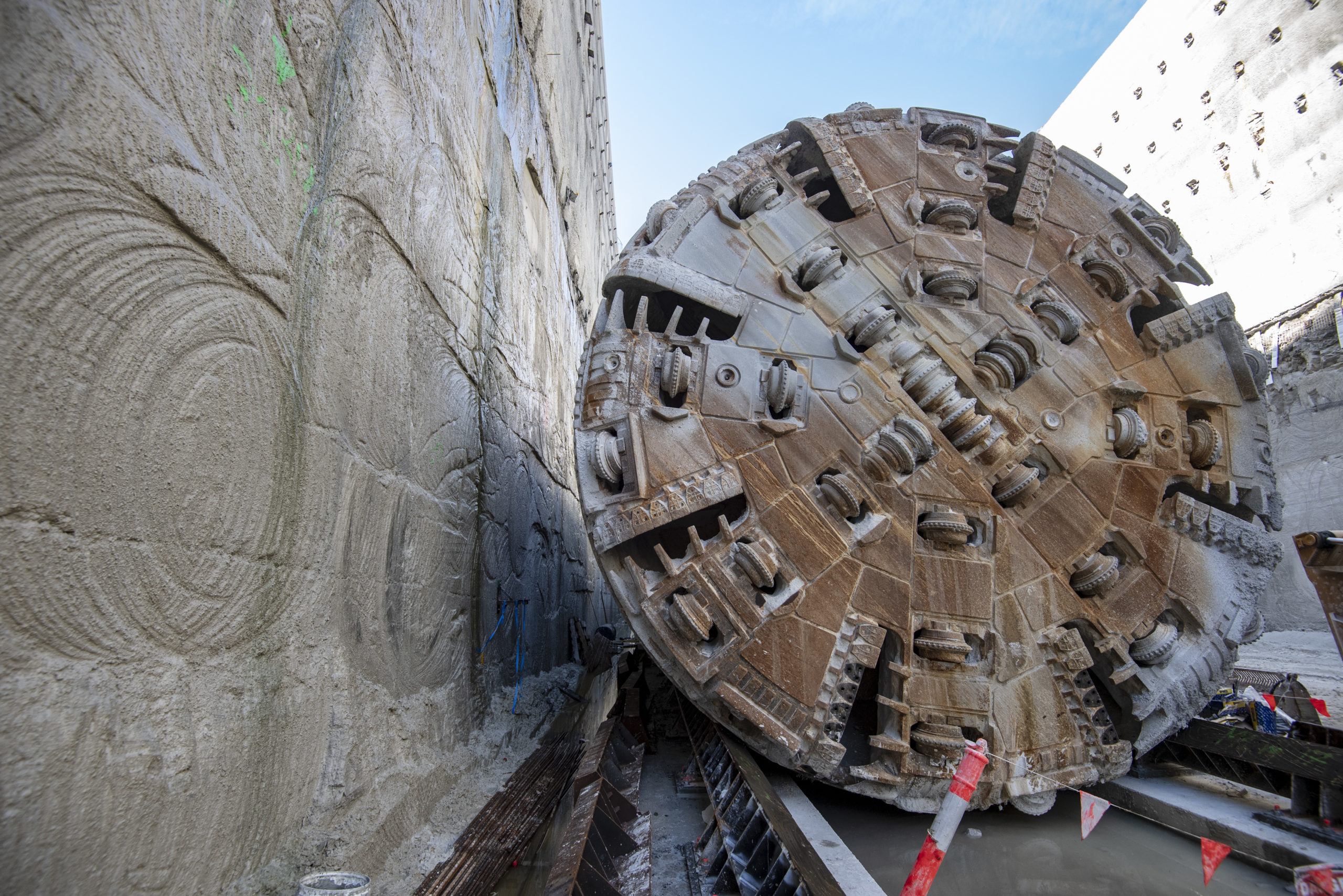
At the end of April 2020, the final TBM drive was completed holing out at Blues Point after it had tunnelled 885 m from Barangaroo, up to 40 m deep under Sydney Harbour.
Supporting the project, VMT has provided equipment and site support for the TBMs, roadheaders and rockbolters with a variety of navigation systems for each of the tunnelling systems types as well as its Segment Documentation System (SDS). The navigations systems were also supported by VMT’s TUnIS Navigation Office software.
The navigation systems include:
- TUnIS Navigation for each of the Double Shield machines
- TUnIS Navigation for the Single Shield machine
- TUnIS Navigation systems for each of the Roadheaders
- TUnIS Navigation systems for each of the Rockbolters
 As well as this more traditional equipment, VMT has also introduced for the first time its TUnIS.mono cam. TUnIS.mono cam was specially designed for the navigation of Double Shield TBMs and is used to determine the position and situation of the front shield in relation to the gripper shield in 3 dimensions by using a camera located in the gripper shield and special targets on the front shield.
On double shield machines, the position and situation particularly of the front shield must be known. From a structural perspective, this is usually very complicated to determine using a conventional laser system. A complex system is used for the relative position and situation determination of the front shield compared to the gripper shield involving multiple components including a laser, laser target, inclinometer and a cylinder stroke measurement system, all of which requires a lot of room and complicated cabling and sensors.
With TUnIS.mono cam, VMT has now created a solution that needs only a single active component and is correspondingly simple to install, saving space and providing a system is unlikely to be problematic.
 TUnIS.mono cam is a complementary system that is used with the main system, a laser-based navigation system. The main system determines the position and situation of the gripper shield. Based on this, TUnIS.mono cam then determines the position and situation of the front shield.
TUnIS.mono cam works photogrammetrically: to do so, an appropriate camera is installed in the gripper shield. Special markers are applied and surveyed in on the front shield. During operation, the system recognises the markers in the camera image and uses them to calculate the 3-dimensional position of the front shield in relation to the known position of the gripper shield. The most modern image measuring software is used for this along with sophisticated calculation algorithms.
The benefits of the new TUnIS.mono cam include:
- The system does not require a laser, laser target, inclinometer or cylinder stroke measurement system, making it a simple, fast and space-saving setup
- Minimal cabling is required in both the front and gripper shields
- It offers continuous availability of current data due to increased measurement frequency
- Reduced repair costs due to lack of damage to susceptible and expensive sensors
- The system is virtually maintenance-free
- Compared to laser-based systems, there is an increased field of vision which means it can be used in tight curves.
 Given this was the first use of the new TUnIS.mono cam, VMT’s Gerlinde Grom interviewed two of John Holland CPB Ghella JV’s senior surveyors, Thomas Pascoe (TP) and Reto Salvisberg (RS), on the effectiveness of the new system.

Senior surveyor Thomas Pascoe
Did you feel comfortable with the navigation system from VMT?
Yes (TP)
Yes (RS)
Did this VMT solution generally fulfil your expectations – did it perform as expected?
Yes (TP)
Yes. I have used many previous versions of the VMT Double Shield Navigation System, and this camera system is a very big improvement. This system works well under all extreme conditions such as high vibration or excessive front shield roll/articulation. (RS)
Did you feel confident in the results offered and the position calculated by the camera system?
Yes (TP)
Yes (RS)
Senior surveyor Reto Salvisberg
Is there anything specific you would like to say about the new system in terms of visibility, cleaning of the system and Tunnel Proofing of the set up?
There was good visibility on the system. The camera system generally was able to track 14 or more system markers even through the tighter curves. Also we did not have to clean the markers as often as I might have expected, occasionally yes but not often. In terms of ‘Tunnel Proofing’ we covered the camera with a protective shield to prevent rock/mud ingress and the system and its mount seemed stable. (TP)
I agree the system has good visibility. Illumination of the markers was available as there was a light mounted beside the camera. Cleaning of the markers was sometimes necessary but not too often. When installing the camera we made sure it had a cover over the top especially as it was mounted directly under the front of the gripper shield. This was necessary as sometimes rocks come through the gap when the front shield was fully extended. (RS)
How was the handling with the navigation system?
System was easy to use. (TP)
This system was easy to use. (RS)
What main benefits did the system deliver and do you have any ‘hard figures’ that prove these benefits such as cost reductions, reduction in staff, time on site etc.?
The position shown by the VMT system was very similar to the wriggle survey taken. This meant the VMT system real-time wriggles were very reliable and useful for possible steering corrections. It was great to have worked with this system and be one of the first to use it exclusively with no backup in place. It offers a very reliable and robust system. (TP)
The hardware was reliable and there was no downtime due to equipment failure. (RS)
How well did the collaboration with VMT work both during the set-up and operational periods?
VMT’s support was good for the start-up and install process. The VMT engineers’ knowledge of system was good as was the training provided to our site surveyors and engineers. During the operational phase from a survey navigation viewpoint the system was easy to use, therefore little input required. Remote support was also available via ‘teamviewer’ which was also helpful. (TP)
Support from VMT was very good at all times during commissioning and during the tunnelling process. (RS)
Would you look to utilise this VMT solution and have VMT as partner again?
Yes and I am looking forward to the next project! (TP)
Yes (RS)
Responding to some of the points highlighted during the interview VMT’s engineer, Gerlinde Grom, Senior Project Engineer at VMT said: “In terms of visibility in total there are 16 markers in the system. To calculate the shield position, we use at least 6 to 8 markers. So, if there are 14 markers or more visible all is well. Our initial design provided for a camera light to illuminate the markers. It was also useful to hear the comment about the camera cover. We will mount this on all installations in future. It was also good to hear that the camera is ‘Tunnel proof’ and that there were no issues due to vibration etc. It was also a good result that the wriggle surveys matched very closely. This shows that the installation of the brackets by the contractor was good which made for a good survey to the front of the TBM, even with the limited space given that the measurement across the TBM gantry was necessary.”
At a Glance Fact Sheet:
|